High Speed ​​Machining (HSM) is one of modern advanced manufacturing technologies. It has the advantages of high cutting efficiency, low cutting force and low cutting heat, small forced cutting vibration, and high processing quality. Its cutting speed, feed speed, and feed acceleration are increased to 5 to 10 times that of ordinary speed cutting. The technical data of the machine tool, cutting tool, and cutting process are very different. Due to the fact that the brand performance of domestic workpiece materials is different from that of foreign countries, the foreign HSM process technology data cannot be completely copied. In order to give full play to the utility of expensive imported HSM equipment and extend the tool life as much as possible, it is urgent to research and develop the HSM technology database that suits the national conditions and provide practical reference tools for domestic enterprises as soon as possible. The following describes the high-speed cutting process database developed through the cooperation of international production, research, and research.
Figure 1 Database System Framework Structure
1 Functions and basic structure of database system The function of the database system is to provide technical technical data query information for the user's actual HSM reference high-speed milling processing to account for 80% of the HSM application, so the database is currently only included in the milling process technology data. As shown in Figure 1, the database system contains two major pieces of software and process technology data. Software design uses the current mainstream tree-structured relational database, compared with hierarchical data or network data models. It has a clear mathematical foundation, strong management functions, and good operability. The software consists of two parts: the back-end database and the user interface. The former is a variety of forms for loading the corresponding technical data, including the geometric information of the workpiece, and the latter is a group of human-machine dialogue frames between the former and the user. The back-end database part of the software is developed on the SQL Server2000 platform of the relational database management system. It is easy to modify and supplement, and it can be extended to an expert system. And support network remote query data information. The user interface is programmed and developed using the VB6.0 programming language. It can fully support the structured query language SQL and is convenient for man-machine dialogue operations. The user interface is linked to the back-end database through the Open Database Connectivity (ODBC) interface developed by Microsoft. ODBC is designed according to SQL rules and can be used as a common interface between various Microsoft programming languages ​​and all database development platforms that accept SQL rules. Part of the HSM process technical data was accumulated through trial cutting in our laboratory, and another part was provided by the Chinese partner companies participating in international cooperation projects, which was the result of their many years of production practice. 2 The back-end database of the software follows the functions specified for the database system. It needs to include the workpiece material, cutting tool, cutting technology, and other data information of the HSM cutting example for future reference. Correspondingly, in the back-end database, it is necessary to create tables of workpiece materials, tools, crafts, and craft pictures to store these information, as shown in FIG. 2 .
Figure 2 Logical structure of data information table
Among them, the workpiece material being processed has a global impact on the HSM process; once the workpiece material changes, the tool material used, cutting process parameters, etc. may have to change. Therefore, when determining the logical relationship between database tables, it is based on the workpiece material table, which leads to the process table, which contains the tool material and the brand number column; through them, the tool detailed information data is further derived. Taking into account the workpiece geometry and size of the HSM process also has a great impact, in the back-end database has set up a process picture table to illustrate the workpiece geometry corresponding to the cutting instance, so that all the data information is more valuable. The artwork picture form is also under the craft form. In order to accurately specify and define the workpiece material to be processed, in addition to knowing its name and brand name as basic identification, it is also necessary to give numerical values ​​of its mechanical properties such as hardness, tensile strength, yield strength, impact value, thermal expansion coefficient, and elongation; The size, by affecting the cutting force and cutting heat, will have a great impact on the HSM process. Based on this, the corresponding columns are set up in the workpiece material table. According to practical experience. After determining the workpiece material, selecting different tool materials and grades will decisively influence the setting of cutting parameters and other process conditions. Therefore, the tool material and the number column are arranged at the beginning of the process table. Considering that the geometric parameters and structural performance information of the tool are many and important, and in turn will be constrained by the workpiece geometry and processing technology, logically it is not appropriate to juxtapose with the process data information. In the back-end database, a separate tool table is established. Below the craft table. The column content of the second sequence in the process table is that when the HSM CNC milling machine is actually operated, the cutting parameters need to be set directly, that is, the spindle speed, the axial cutting depth, the feed speed, and the radial cutting depth, ie, the row spacing of the knife. Since the cutting speed is a representative process parameter of HSM, the feed rate per tooth of the milling cutter is also an important cutting parameter. The corresponding columns are added in the process table, and they are converted by the back-end database to display and provide reference. In addition, there are columns that describe other process conditions such as cooling lubrication. HSM is mainly used for half tip and tip processing of steel and hard-to-cut materials, as well as all coarse and fine machining of free-cutting materials such as aluminum, copper, engineering plastics, and graphite. In order to take into account the diversity of the process, the back-end database's process table is classified according to roughing and finishing. In the latter, machining accuracy and surface roughness are added. The last column in the process table is the process picture number, which is used to derive the process picture table. The technical parameters of the process are related to the geometric information of the processed workpiece. In the craft picture table, there are only two columns of the craft picture number and the craft picture. The former corresponds to the process sheet and the latter refers to the physical address where the artwork is placed. The image is displayed when the user invokes it. In the tool table, the first two columns are the tool material and the brand. Also linked to the process sheet. Then, according to actual needs, a total of more than ten columns of tool names, geometric and physical parameters, use restriction parameters, configuration, and manufacturing suppliers were established, and they can be added or removed at any time in the future.
Figure 3 Material Table under SQL Server 2000 Platform
In order to improve the retrieval efficiency and reduce the total amount of data information, only one piece of data information corresponding to the name of the HSM cutting example is loaded into each sheet of FIG. 2 to form a record. In other words, all HSM instance data information is stored in 4 tables. A total of 4 records are used, and only one of the rough and fine processing can be selected. By setting up a primary key in each table, that is, a column with a key symbol in Fig. 2, its contents can neither be duplicated nor vacant, and must be indicated when unknown, as shown in Fig. 3, and by setting up a search index, that is, The same columns appear in the two tables, which allows one piece of data information in the workpiece material, process picture, and tool table to be recorded and linked to multiple records in the process table. In this way, duplicate records in the first 3 tables are avoided and the number can be reduced accordingly. It will play an important role in the future when the total amount of data information is large. On the other hand, it also ensures that each record in the process table is linked with each record in the other three tables as a whole, which can prevent redundant data information from appearing.
Figure 4 database software running process
3 Software user interface The user interface of software visualization is divided into main interface, user query interface and management interface. Their role in man-machine dialogue operation software program is shown in Figure 4. All walks of life have a drop-down menu or mouse button that is commonly used in Microsoft software to provide users with a click-to-click option for ease of use. After starting the database software, the user first comes to the main interface and can see the name of the unit participating in the research and development database system, and enters the query interface or the management interface respectively through the mouse button. The user needs to exit the program when he finishes the work, and also goes through the main interface under normal circumstances. After the user enters the query interface, you first need to select or enter the name of the workpiece material. The mouse or keyboard action automatically retrieves all the information records that match the material name from the material table of the back-end database through the ODBC interface, and returns them through the ODBC interface to display on the query interface. Then, you need to click to select one of the material brands and select roughing or finishing. Through the contact and interaction of the query interface with the back-end database, the retrieved process information record will be displayed on the query interface, or no corresponding record will be indicated. At this point, you need to re-select for finishing or roughing. For the former case, it is necessary to continue to click to select the number of the knife or the number of the craft picture, and then complete the operation of retrieving the tool information and the process picture information in order. Craft pictures can also be magnified. Figure 5 shows the user query interface. In the above process, you can interrupt the current operation at any time and return to the retrieval of any previous information, such as giving up the last tool information retrieval directly back to the selection or inputting the next material name from the beginning. Once you have retrieved the required data information, you can click the button in the upper left corner of the query interface to enter the information output interface, print them out in the screen display style, or use Microsoft Office document image (.mdi), web page (html), Various file formats such as text (txt) are exported. The data information can also be viewed in the UNIX operating system or in the CNC machine tool system. In order to facilitate the modification of process technology data and maintenance systems, the software has added a management interface. Type the password into the management community, and then you can add, update, or even delete data information directly in the software program running state, without having to end the program running into the SQL Server2000 platform to complete the operation.
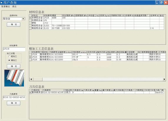
Figure 5 user query interface
4 Process Technology Data Accumulation Database system HSM process technology data currently involves workpiece materials such as aluminum alloys, copper alloys, steel, cast iron, and paper-based honeycomb cores. Milling cutter materials mainly include carbide and diamond. Among them, an automobile engine factory and other use of diamond milling cutter to high-speed milling more than 3900m/min line rate casting aluminum alloy workpiece, not only processing quality and efficiency, but also long tool life, and achieved good economic results. Another example is the use of TiAlN coated carbide cutters for high speed hard milling of hardened steel moulds with a hardness of 52 HRC. The line speeds exceed 200 m/min, and the surface roughness reaches Ra 0.33 μm, and the processing time is saved. In these HSM cutting examples, the spindle speed of the machine tool is correspondingly up to 15,000 to 28,000 r/min. Another representative cutting data, the feed rate, reaches 6 to 8 m/min in many machining examples. As far as the geometry of the workpiece is concerned, there are multi-bar thin-walled integral structural parts in the machining examples, and the material removal rate is as high as 80% or more. It is necessary to strive to control the processing distortion and increase the efficiency, and the paper-based honeycomb core core test pieces need to use special materials. Fixtures and cutters. In addition, there are complex three-dimensional free-form surfaces in the example, which need to be processed by four-axis or even five-axis CNC milling. The continuous accumulation of HSM process technology data will continue to proceed from these two aspects. 5 Looking forward to the database of high-speed cutting processes, the Chinese partner companies participating in international cooperation projects have now submitted their trials. By extensively listening to opinions and preparing for the further support and cooperation of national, local government and domestic enterprises, we will expand it into a high-speed cutting process expert system that can be remotely accessed through the Internet.
Polypropylene Fabrication
Polypropylene is a thermoplastic belonging to the polyolefin group. Wuxi Yuda Plastic Welding Machinery provides welding equipment to handle all diameter sizes offered and has an extensive line of fusion machines available to buy for every application. Polypropylene pipe can be bent in the field, also polypropylene fabrication of plastics can be made like HDPE in workshops.
Polypropylene (PP) Pipe and Fittings assembly and joining of this system is performed by heat fusion. Fusion joints are made by heating and melting the pipe and fitting together. This type of joint gives a homogeneous transition between the two components without the lowering of chemical resistance associated with solvent cement joining and without the loss of integrity and loss of pressure handling ability of a threaded joint.
Five different fusion methods for Polypropylene Piping Systems are available and commonly used in today`s demanding applications. These include conventional socket fusion, electrofusion, conventional contact butt fusion.
For Polypropylene Pipe Fabrication, it can use Yuda Workshop Fitting Welding Machines and Plastic Pipe Saw. Polypropylene (PP) is a partly crystalline thermoplastic similar to HDPE. Both of them have same welding process but in different welding temperature. For more information for PP Fusion Welders, feel free to contact Wuxi Yuda Plastic Pipe Welding Machinery Factory
Polypropylene Fabrication,Hdpe Pipe Fabrication,Polyethylene Welder,Polypropylene Welding Machine
WUXI MEIERTE MACHINERY TECHNOLOGY CO.,LTD , https://www.pipefusionweldings.com