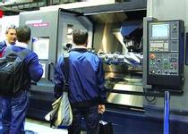
 High-speed feed system based on parallel (virtual axis) mechanism:
 Conventional machine tools work in Cartesian coordinates. The most typical layout of this type of machine tool is to mount the workpiece on an orthogonal table to realize the movement of the X and Y axes; to install the spindle components on the column slide to achieve Z-axis movement. The total mass of the moving part (workpieces, fixtures, worktables, etc.) of such a machine tool is large, and the drag generated by the multi-layer guide rails makes it difficult for the machine tool to achieve a very high feed rate and acceleration. In addition, the traditional machine tool is a series system, which has many components and complicated structure, and often has cantilever components and joint gaps. Therefore, it is difficult for the machine tool to obtain high rigidity. The emergence of parallel (virtual axis) machine tools has opened up a new way to solve the above problems.
Each rod is driven by a ball screw or a linear motor to adjust and control the different lengths of the six rods (real axis), so that the tool on the spindle can move 6 degrees of freedom, and it is installed on the fixed work Workpieces on a table (not shown in the figure). This structure was proposed in the 1960s, but since all six real axes that affect the main shaft must move, the calculations are extremely complicated and there was no way to produce it at that time. Only when CNC technology is highly developed today, the application of parallel machine tools has become possible, and a variety of design solutions have emerged. The main advantages of this parallel mechanism feed system are as follows:
(1) High feed rate At the same motor drive speed, the space parallel mechanism can obtain a higher feed rate than the conventional machine tool's series mechanism. The parallel machine tool does not have a table and its supporting parts that move along the fixed guide rails, and eliminates the frictional resistance of the guide rail pair, which is advantageous to the further increase of the feed speed.
(2) High acceleration The workpiece on the machine is fixed and all coordinate movements are performed by a 6-pole electric spindle. The mass of the moving parts is small, and the driving force of the tool is the combined force of the six rods, so the driving force is large, and it is easy to obtain a high feed motion acceleration.
(3) Stiffness The drive rod is not only the transmission component of the machine tool, but also the support component of the spindle unit, which reduces the connection link and transmission gap of the "machine tool-tool-workpiece" process system, and cancels the cantilever structure of the conventional machine tool. The bar is only subject to bending moments, which greatly increases the overall stiffness of the machine. This parallel feed system also has the following disadvantages: There are more axes and six axes are required for linear motion. Therefore, the programming is more complicated and the operation is not intuitive. The length of the 6 rods is large and the thermal deformation has a serious effect on the machining accuracy. Therefore, the current machining accuracy is not too high; the effective space for processing is not commensurate with the proportion of the machine tool itself, and it also limits its processing capability. All these problems have yet to be resolved.
Shrink Tunnel Packing Machine,Small Shrink Tunnel Packing Machine,High Speed Shrink Tunnel Packing Machine,Auto Shrink Tunnel Packing Machine
Ningbo Yongfu Textile Machinery Co., Ltd. , http://www.yfwinders.com