Minimizes Costs- Maximizes Flexibility- Optimizes Distribution
√  3-speed centrifugal fan statically and dynamically balanced (for AC version)
√  EC Motor with modulating 0-5 V DC Input(for EC version)
√  Auxiliary Electric Heater Element for installation On-site or In-stock
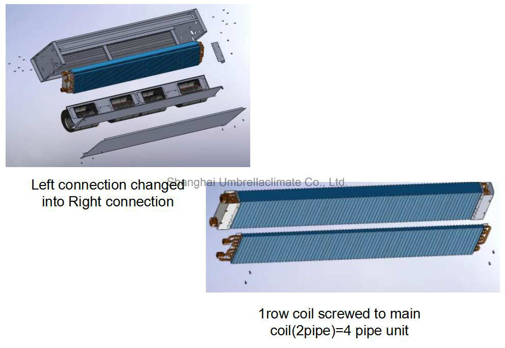
√  Interchangeable left/right side coil connections
√  Auxiliary 1 row heating coil for installation On-site or in-stock
√  12,30 and 60 Pa External Static Pressure(ESP) models available (for AC version)
√  Variable External Static Pressures(ESP)up to 60 Pa(for EC version)
AC model + EC model
2 pipe fromÂ
Cooling: Â 1.7 kw ~ 9.9 kw
Heating: 2.04 kw ~11.7kw
4 pip from
(with heating coil)
Cooling: 1.7 kw ~ 9.9 kw
Heating:1.9 kw ~ 10.2 kw
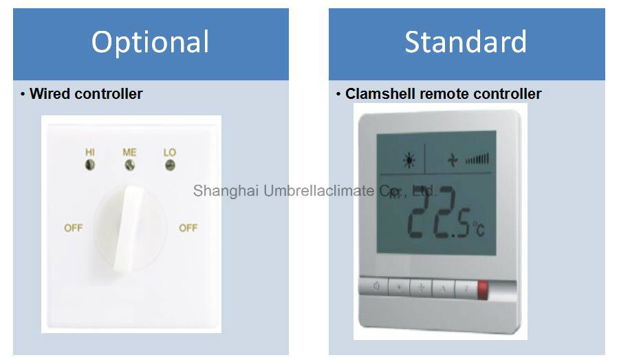
Controller
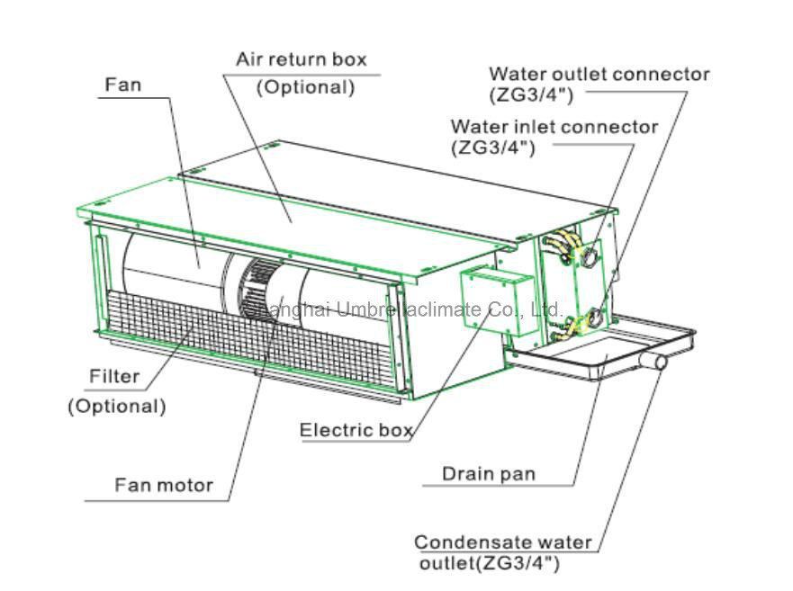
FCU Breakdown:
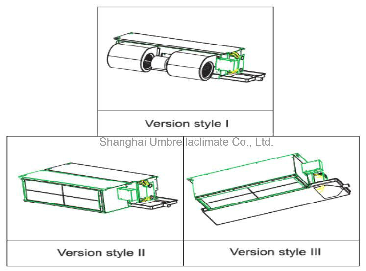
FCU Version:
MULTIPLE FUNCTION:
Production View:
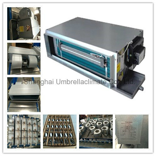
FCU Technical Data:
| Â | Â | FC-WA(3R)-[Size]-V~ | 200 | 300 | 400 | 500 | 600 | 800 | 1000 | 1200 | 1400 | 1600 | |||
| Unit Configuration | Configuration | 2-pipe | |||||||||||||
| Number Of Fan Blowers | Single | Twin | Three | Four | Three | Four | |||||||||
| Power Supply | (V/Ph/Hz) | 230 / 1 / 50 | |||||||||||||
| 220Â /Â 1Â /Â 60 | |||||||||||||||
| Operation Control | ~S: Complete function onboard PCB with integrated group control functionality, incl. 1 pc return air sensor and 2 pcs temperature sensors. | ||||||||||||||
| ~T: Terminal strip only. | |||||||||||||||
| Performance Data | Air | Air Flow | H | 3 | m3/hr | 451 | 566 | 758 | 934 | 1179 | 1527 | 1754 | 1991 | 2586 | 2933 |
| M | 2 | 358Â | 457Â | 615Â | 840Â | 958Â | 1220Â | 1605Â | 1871Â | 2389Â | 2666Â | ||||
| L | 1 | 278Â | 293Â | 433Â | 571Â | 779Â | 896Â | 1144Â | 1573Â | 2068Â | 2482Â | ||||
| Available pressure | H | 3 | Pa | 75 | 75 | 75 | 75 | 75 | 75 | 75 | 75 | 75 | 75 | ||
| M | 2 | 75 | 75 | 75 | 75 | 75 | 75 | 75 | 75 | 75 | 75 | ||||
| L | 1 | 75 | 75 | 75 | 75 | 75 | 75 | 75 | 75 | 75 | 75 | ||||
| Cooling | Cooling Capacity | H | 3 | Kw | 2.43 | 3.08 | 3.9 | 4.8 | 5.99 | 8.01 | 8.72 | 9.87 | 12.8 | 14.6 | |
| M | 2 | 2.02 | 2.59 | 3.3 | 4.42 | 5.09 | 6.7 | 8.14 | 9.4 | 12 | 13.5 | ||||
| L | 1 | 1.65 | 1.8 | 2.5 | 3.24 | 4.32 | 5.23 | 6.23 | 8.2 | 10.7 | 12.8 | ||||
| Sensible Cooling Capacity | H | 3 | 1.74 | 2.2 | 2.82 | 3.46 | 4.31 | 5.73 | 6.35 | 7.16 | 9.24 | 10.5 | |||
| M | 2 | 1.44 | 1.84 | 2.38 | 3.18 | 3.64 | 4.77 | 5.91 | 6.81 | 8.66 | 9.71 | ||||
| L | 1 | 1.17 | 1.27 | 1.78 | 2.31 | 3.08 | 3.7 | 4.48 | 5.92 | 7.71 | 9.16 | ||||
| Heating | Heating Capacity | H | 3 | Kw | 3.00 | 3.78 | 4.87 | 5.99 | 7.43 | 9.85 | 11.00 | 12.52 | 16.15 | 18.25 | |
| M | 2 | 2.50Â | 3.18Â | 4.12Â | 5.51Â | 6.32Â | 8.24Â | 10.27Â | 11.92Â | 15.14Â | 16.66Â | ||||
| L | 1 | 2.04 | 2.21 | 3.12 | 4.04 | 5.36 | 6.43 | 7.86 | 10.4 | 13.5 | 16 | ||||
| Max. Electric Heater Capacity@220V | 1 | 1 | 3 | 3 | 3 | 3 | 3 | 3 | 3 | 3 | |||||
| Sound | Sound Pressure Level ( Outlet ) | dB(A) | 40/38/37 | 44/43/40 | 43/41/37 | 45/43/39 | 49/47/44 | 44/43/39 | 47/46/44 | 52/48/44 | 52/48/44 | 54/52/50 | |||
| Sound Pressure Level ( Inlet + Radiated ) | 43/41/40 | 47/46/43 | 46/44/40 | 48/46/42 | 52/50/47 | 47/46/42 | 50/49/47 | 55/51/47 | 55/51/47 | 57/55/53 | |||||
| Sound Power Level ( Outlet ) | 49/47/46 | 53/52/49 | 52/50/46 | 55/53/48 | 58/56/51 | 53/52/48 | 57/56/53 | 61/57/54 | 61/57/53 | 63/61/60 | |||||
| Sound Power Level( Inlet + Radiated ) | 52/50/49 | 56/55/52 | 55/53/49 | 58/56/51 | 61/59/54 | 56/55/51 | 60/59/56 | 64/60/57 | 64/60/56 | 66/64/63 | |||||
| Electrical | Fan Motor Power | H | 3 | W | 82 | 105 | 139 | 154 | 206 | 261 | 288 | 359 | 430 | 511 | |
| M | 2 | 75Â | 96Â | 128Â | 146Â | 188Â | 238Â | 276Â | 342Â | 365Â | 460Â | ||||
| L | 1 | 68Â | 88Â | 111Â | 129Â | 173Â | 216Â | 249Â | 325Â | 345Â | 412Â | ||||
| Fan Motor Running Current @ H | A | 0.36 | 0.46 | 0.61 | 0.67 | 0.93 | 1.14 | 1.22 | 1.61 | 1.95 | 2.33 | ||||
| Fan Motor Starting Current @ H | A | 1.08 | 1.14 | 1.35 | 1.95 | 2.10 | 2.70 | 3.52 | 4.81 | 5.65 | 6.75 | ||||
| Hydraulic | Cooling Water Flow Rate | 3 | L/h | 417 | 528 | 669 | 827 | 1029 | 1375 | 1498 | 1694 | 2197 | 2501 | ||
| 2 | 347 | 445 | 567 | 758 | 873 | 1150 | 1397 | 1613 | 2064 | 2321 | |||||
| 1 | 283 | 310 | 428 | 557 | 741 | 898 | 1069 | 1408 | 1842 | 2194 | |||||
| Cooling Pressure Drop | 3 | KPa | 18.3 | 30.8 | 17 | 26.7 | 42.8 | 42.7 | 17.3 | 22.7 | 42.2 | 57.2 | |||
| 2 | 13.3 | 22.9 | 12.8 | 23.1 | 32.1 | 31.3 | 15.4 | 20.8 | 37.9 | 50.2 | |||||
| 1 | 9.38 | 12.3 | 7.9 | 13.6 | 24.2 | 20.4 | 9.68 | 16.5 | 31.1 | 45.5 | |||||
| Heating Water Flow Rate | L/h | Same as "Cooling Water Flow Rate" | |||||||||||||
| Heating Pressure Drop | 3 | KPa | 14.75 | 24.82 | 13.7 | 21.6 | 35 | 24.8 | 14 | 18.6 | 34.7 | 47.4 | |||
| 2 | 10.72 | 18.45 | 10.3 | 18.7 | 26.3 | 25.5 | 12.5 | 17 | 31.2 | 41.6 | |||||
| 1 | 7.56 | 9.91 | 6.36 | 11 | 19.8 | 16.6 | 7.85 | 13.5 | 25.6 | 37.7 | |||||
| water content | L | 0.72 | 0.87 | 1.02 | 1.17 | 1.32 | 1.92 | 2.07 | 2.22 | 2.59 | 2.84 | ||||
| Construction and Packing Data | Water | Type | Socket(Threaded Female) | ||||||||||||
| Connections | In |  mm [in] | 3/4" | ||||||||||||
| Â | Out | ||||||||||||||
| Condensate Drainage Connection | |||||||||||||||
| Dimensions | L | mm | 755Â | 855Â | 955Â | 1155Â | 1255Â | 1655Â | 1755Â | 1855Â | 1755Â | 1955Â | |||
| W | 550Â | 620Â | |||||||||||||
| H | 250Â | 300Â | |||||||||||||
| Net Weight | Kg | 17 | 23 | 24 | 28 | 31 | 36 | 43 | 45 | 51 | 60 | ||||
a. Cooling mode: Â Â Â Â Â Â Â Â Â Â Â Â Â Â Â Â Â Â Â Â Â Â Â Â Â Â Â Â Â Â Â Â Â Â Â Â Â Â Â Â Â Â b. Heating mode:Â Â Â Â Â Â Â Â Â
                       Â
- Return air temperature: 27C DB/ 19C WB.                         - Return air temperature: 20C.        Â
- Inlet/ outlet water temperature: 7C/ 12C.                          - Inlet water temperature: 50C.        Â
                                                        - Water flow-rate: same as cooling mode  Â
 Ceiling Concealed Fan Coil Unit (HVAC Terminal FCU)
Minimizes Costs- Maximizes Flexibility- Optimizes Distribution
√  3-speed centrifugal fan statically and dynamically balanced (for AC version)
√  EC Motor with modulating 0-5 V DC Input(for EC version)
√  Auxiliary Electric Heater Element for installation On-site or In-stock
√  Interchangeable left/right side coil connections
√  Auxiliary 1 row heating coil for installation On-site or in-stock
√  12,30 and 60 Pa External Static Pressure(ESP) models available (for AC version)
√  Variable External Static Pressures(ESP)up to 60 Pa(for EC version)
AC model + EC model
2 pipe fromÂ
Cooling: Â 1.7 kw ~ 9.9 kw
Heating: 2.04 kw ~11.7kw
4 pip from
(with heating coil)
Cooling: 1.7 kw ~ 9.9 kw
Heating:1.9 kw ~ 10.2 kw
Controller

FCU Breakdown:

FCU Version:

MULTIPLE FUNCTION:

Production View:

FCU Technical Data:
| Â | Â | FC-WA(3R)-[Size]-V~ | 200 | 300 | 400 | 500 | 600 | 800 | 1000 | 1200 | 1400 | 1600 | |||
| Unit Configuration | Configuration | 2-pipe | |||||||||||||
| Number Of Fan Blowers | Single | Twin | Three | Four | Three | Four | |||||||||
| Power Supply | (V/Ph/Hz) | 230 / 1 / 50 | |||||||||||||
| 220Â /Â 1Â /Â 60 | |||||||||||||||
| Operation Control | ~S: Complete function onboard PCB with integrated group control functionality, incl. 1 pc return air sensor and 2 pcs temperature sensors. | ||||||||||||||
| ~T: Terminal strip only. | |||||||||||||||
| Performance Data | Air | Air Flow | H | 3 | m3/hr | 451 | 566 | 758 | 934 | 1179 | 1527 | 1754 | 1991 | 2586 | 2933 |
| M | 2 | 358Â | 457Â | 615Â | 840Â | 958Â | 1220Â | 1605Â | 1871Â | 2389Â | 2666Â | ||||
| L | 1 | 278Â | 293Â | 433Â | 571Â | 779Â | 896Â | 1144Â | 1573Â | 2068Â | 2482Â | ||||
| Available pressure | H | 3 | Pa | 75 | 75 | 75 | 75 | 75 | 75 | 75 | 75 | 75 | 75 | ||
| M | 2 | 75 | 75 | 75 | 75 | 75 | 75 | 75 | 75 | 75 | 75 | ||||
| L | 1 | 75 | 75 | 75 | 75 | 75 | 75 | 75 | 75 | 75 | 75 | ||||
| Cooling | Cooling Capacity | H | 3 | Kw | 2.43 | 3.08 | 3.9 | 4.8 | 5.99 | 8.01 | 8.72 | 9.87 | 12.8 | 14.6 | |
| M | 2 | 2.02 | 2.59 | 3.3 | 4.42 | 5.09 | 6.7 | 8.14 | 9.4 | 12 | 13.5 | ||||
| L | 1 | 1.65 | 1.8 | 2.5 | 3.24 | 4.32 | 5.23 | 6.23 | 8.2 | 10.7 | 12.8 | ||||
| Sensible Cooling Capacity | H | 3 | 1.74 | 2.2 | 2.82 | 3.46 | 4.31 | 5.73 | 6.35 | 7.16 | 9.24 | 10.5 | |||
| M | 2 | 1.44 | 1.84 | 2.38 | 3.18 | 3.64 | 4.77 | 5.91 | 6.81 | 8.66 | 9.71 | ||||
| L | 1 | 1.17 | 1.27 | 1.78 | 2.31 | 3.08 | 3.7 | 4.48 | 5.92 | 7.71 | 9.16 | ||||
| Heating | Heating Capacity | H | 3 | Kw | 3.00 | 3.78 | 4.87 | 5.99 | 7.43 | 9.85 | 11.00 | 12.52 | 16.15 | 18.25 | |
| M | 2 | 2.50Â | 3.18Â | 4.12Â | 5.51Â | 6.32Â | 8.24Â | 10.27Â | 11.92Â | 15.14Â | 16.66Â | ||||
| L | 1 | 2.04 | 2.21 | 3.12 | 4.04 | 5.36 | 6.43 | 7.86 | 10.4 | 13.5 | 16 | ||||
| Max. Electric Heater Capacity@220V | 1 | 1 | 3 | 3 | 3 | 3 | 3 | 3 | 3 | 3 | |||||
| Sound | Sound Pressure Level ( Outlet ) | dB(A) | 40/38/37 | 44/43/40 | 43/41/37 | 45/43/39 | 49/47/44 | 44/43/39 | 47/46/44 | 52/48/44 | 52/48/44 | 54/52/50 | |||
| Sound Pressure Level ( Inlet + Radiated ) | 43/41/40 | 47/46/43 | 46/44/40 | 48/46/42 | 52/50/47 | 47/46/42 | 50/49/47 | 55/51/47 | 55/51/47 | 57/55/53 | |||||
| Sound Power Level ( Outlet ) | 49/47/46 | 53/52/49 | 52/50/46 | 55/53/48 | 58/56/51 | 53/52/48 | 57/56/53 | 61/57/54 | 61/57/53 | 63/61/60 | |||||
| Sound Power Level( Inlet + Radiated ) | 52/50/49 | 56/55/52 | 55/53/49 | 58/56/51 | 61/59/54 | 56/55/51 | 60/59/56 | 64/60/57 | 64/60/56 | 66/64/63 | |||||
| Electrical | Fan Motor Power | H | 3 | W | 82 | 105 | 139 | 154 | 206 | 261 | 288 | 359 | 430 | 511 | |
| M | 2 | 75Â | 96Â | 128Â | 146Â | 188Â | 238Â | 276Â | 342Â | 365Â | 460Â | ||||
| L | 1 | 68Â | 88Â | 111Â | we are OEM tubing pipeline factory ,we could produing what you need ,for car use ,waiting for your request in anytime. Polyamide brake tube,PA corrugated tube, Automobile wire tube Changchun FAW Sihuan Automobile Pipe Co,Ltd , https://www.automobilepipe.com | ||||||||||