The temperature of each part during the operation of the transformer is not the same, the temperature of the coil is the highest, followed by the temperature of the iron core, and the temperature of the insulating oil is lower than the temperature of the coil and the iron core. The upper oil temperature of the transformer is higher than the lower oil temperature. Permissible temperature in transformer operation is checked against the upper oil temperature. For Class A insulated transformers in normal operation, when the ambient air temperature is up to 400C, the transformer winding's limit operating temperature is 1050C. Since the winding temperature is 100C higher than the oil temperature, in order to prevent deterioration of the oil quality, the maximum oil temperature in the upper layer of the transformer is not to exceed 950C. Under normal circumstances, in order to prevent over-speed oxidation of the insulating oil, the upper oil temperature should not exceed 850C. For transformers that use forced oil circulating water cooling and air cooling, the upper oil temperature should not exceed 750C. (This transformer upper oil temperature maximum allowable value is 800C)
Second, allowing temperature rise to monitor only the upper oil temperature in the transformer operation, but also can not guarantee the safe operation of the transformer, but also must monitor the temperature difference between the upper oil temperature and cooling air - temperature rise. The difference between the transformer temperature and the ambient air temperature is called the temperature rise of the transformer. For class A insulated transformers, when the ambient maximum temperature is 400C, the national standard specifies that the temperature rise of the windings is 650C, and the allowable temperature rise of the upper oil temperature is 550C. As long as the temperature rise of the transformer does not exceed the specified value, the transformer can be guaranteed to operate safely within the specified operating years under the rated load. (Transformer can operate continuously for 20 years with rated load during normal operation)
Third, the reasonable capacity In normal operation, the transformer should bear the power load in the transformer's rated capacity of about 75-90%.
Fourth, the transformer unbalanced current maximum voltage shall not exceed 25% of the rated value; transformer power supply voltage change allowed range is 5% of the rated voltage.
If more than this range should be used to adjust the tap switch, so that the voltage reaches the specified range. (Adjustment should be performed when the power is cut off.) Usually, the position of the primary tap tap is changed to realize voltage regulation. The device that connects and switches the tap position is called the tap changer. It adjusts the ratio by changing the number of turns of the high voltage winding of the transformer. of. The low voltage has no effect on the transformer itself, but only reduces some output, but has an impact on the power equipment; the voltage increases, the magnetic flux increases, the iron core saturates, the core loss increases, and the transformer temperature increases.
V. Overload The overload is divided into normal overload and accident overload. Normal overload is caused by the increase in electricity consumption of the user under normal power supply conditions. It will cause the temperature of the transformer to rise, which will lead to accelerated aging of the transformer insulation and reduced service life, so under normal circumstances no overload operation is allowed. In special circumstances, the transformer may operate under overload for a short period of time, but the rated load may not exceed 30% during the winter and 15% of the rated load during the summer. In addition, the transformer's overload capacity should be determined based on the transformer's temperature rise and manufacturer's regulations.
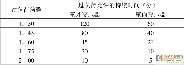
When an accident occurs in the power system or the user substation, in order to ensure continuous power supply to important equipment, the transformer is allowed to run for a short period of time, that is, the accident is overloaded. When the accident is overloaded, the coil temperature will exceed the permissible value. Therefore, for the insulation, Aging faster than normal conditions. However, there is little chance of accident overload. Under normal circumstances, the transformer is under-loaded, so short-term overload causes damage to the insulation of the transformer. The time and multiple of the accident overload should be implemented according to the manufacturer's regulations. If there is no manufacturer's data, the following values ​​can also be referenced.
Accident overload times and times allowed for natural cooling oil-immersed transformers

Dry transformer accident overload multiples and time (for indoor use)

Type: open, closed, cast.
This kind of transformer is used for safety and fire prevention. The open type is a common type. Its body is open to the atmosphere and is suitable for a relatively dry and clean indoor environment. Painting, body transformer substation belongs to this kind.
6. Q&A: What are the reasons for the increase in the temperature of the transformer during operation?
Divided into two kinds of external and internal factors.
External factors: Over-time overload or cooling ventilation is not good.
Internal factors: 1. Insulation damage between the transformer iron core silicon wafers increases the no-load loss of the transformer and increases the temperature of the transformer.
2. Insulation damage to the windings of the transformer causes a short circuit between the turns, resulting in arcing and heating, which increases the temperature of the transformer.
3, bad tapping switch, contact resistance increases and heat, so that the transformer temperature increases.
4, poor contact between the internal and external wiring of the bushing.
Non Standard Custom Finned Tube
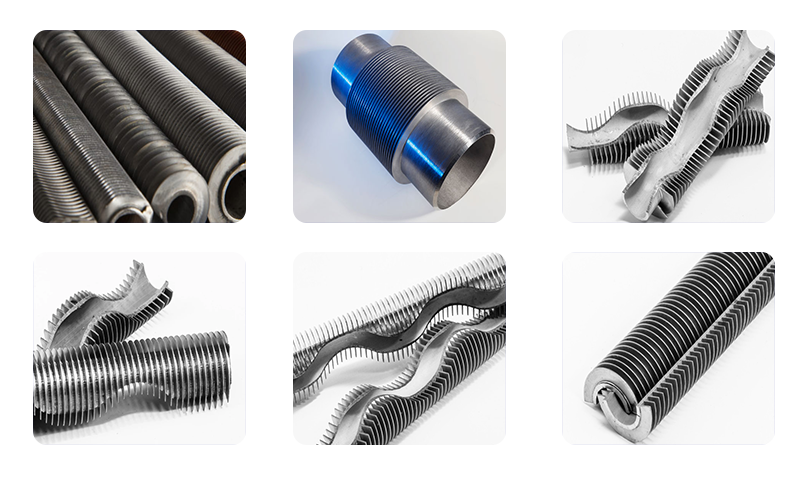
Divided according to the fin structure characteristics: according to the shape and structure of the fin shape, finned tubes can be divided into the following categories, square finned tubes, spiral finned tubes, longitudinal finned tubes, etc., spiral serrated finned tubes, inner finned tubes Tube. Because the suit process is simple, the skill requirements are not high, the equipment used is cheap, and it is easy to maintain, so it is still used by many factories until now.

Our company has accumulated many years of experience in high-frequency welding finned tubes, square finned tubes, inlaid finned tubes, and rolling composite steel and aluminum finned tubes.
Laser welded spiral finned tubes are used in civil wall-hung boilers, industrial boilers, etc., using German technology, which has a history of more than ten years in Europe. The advantage is that the contact thermal resistance is zero, and compared with high-frequency welding Light, small thermal resistance, high penetration rate, and the assembled heat exchanger has the characteristics of compact size, more energy saving and environmental protection, and meets the national emission requirements
Non Standard Customization,Finned Tube With Small Weld,Environmentally Friendly Finned Tube
Wuxi Mcway Equipment Technology Co., LTD , https://www.mcwayfinnedtube.com